This Capcom Service Bulletin applies to:
Pinball Magic, Airborne, Breakshot, Flipper Football, & KingPin Pinball
Back to all Capcom Pinball Service Bulletins
 COIN-OP, INC.
(Pinball Division is out of business)
COIN-OP, INC.
September 27, 1996
Re: Printer Kit Installation
Instructions
Dear Distributor,
This letter is to inform you on the
procedure to install a printer port in your pinball game.
Parts list:
|
QTY |
DESCRIPTION |
PART
NUMBER |
|
1 |
RS232/coin meter/ptr PCB |
A0019501 |
|
1 |
Cable, Interface, Printer (And
mounting hardware) |
C-00195 |
|
1 |
Serial data cable |
C-00197 |
|
4 |
Screw |
SC00121-08 |
|
4 |
Spacer |
PL00108-04 |
Tools needed
#2 Phillips screwdriver
1/4” nut driver
Cable Ties
Side Cutters
Procedure
1. Inventory
physical parts against the parts list above.
Please contact your local CAPCOM Distributor regarding any missing or
damaged parts.
2. Turn power
off to the game and unplug it from the wall.
3. Open the
coin door, and remove the playfield glass hold down bracket.
4. Carefully
remove the playfield glass and set it in a safe location.
5. Locate the
key to the backbox. Insert the key into
the lock at the top of the backbox and turn it fully clockwise. Lift up on the backglass and swing it out
towards the front of the game.
Carefully remove the backglass and set it aside in a safe place.
6. Open the
dot matrix display panel by pushing the two latches, located above the speaker
enclosures, out towards the sides of the backbox. Now lower the display panel.
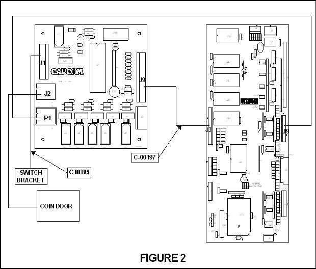
7. Connect
the serial data cable (C-00197) to connector J3 on the CPU PCB.
8. Route the
cable around the CPU board dressing the cable to existing cable with 2 cable
ties at the corners of the CPU PCB and cable clamps.
9. Route the
cable through the bottom of the backbox into the bottom cabinet.
10. Close and
latch the dot matrix display panel.
11. Raise the
playfield to its’ vertical position.
12. Run the
cable along the inside left wall until it reaches the coin door. Make sure that the cable will not be pinched
in the backbox. Use wire ties to secure
the cable approximately every 6”.
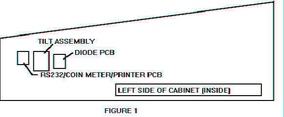
13. Attach the
RS232/coin meter/printer PCB (with the screws, SC00121-08, and spacers,
PL00108-04, provided) to the inside left wall.
Refer to figure 1 for the
proper location.
14. Connect
the serial data cable (the other end was just connected to the CPU in STEP 7)
to connector J9 on the RS232 PCB. Refer
to FIGURE 2 for proper wiring connections.
15. Trace the
wiring from the coin door back into the cabinet to a Molex connector.
16. Separate
the connector into its’ respective halves.
Now connect the male connector to the female connector (P1) on the RS232
PCB and the female connector to the male connector (J2) also on the RS232
PCB. Refer to FIGURE 2 for proper
wiring connections.
17. Connect
the printer interface cable, C00195, to J1 on the RS232 PCB. Mount the other end of the cable, which has
a DB9 type connector, in the slot in the switch bracket with the supplied
mounting hardware. Refer FIGURE 2 for
proper wiring connections.
18. Lower the
playfield and reinstall the backglass, playfield glass, and glass
holddown. Make sure the backglass is
locked and secured.