The pinball magic manual lists these 2 connectors as:
| Wire Path from "Power board" to "CPU board" | |
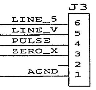
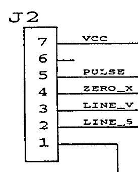
| "Power board" J3.3 (pg 157/199) | "CPU board" J2.4 (pg 166/199) |
 |
 |
Usually it is a wire or connector issue. However, blown circuitry can also be the cause (if you are really unlucky).
The first thing to do is to turn "off" power and visually inspect the ZERO_X wire from one connector to the other connector. If the wire is intact, is not pinched, or cut, or broken. Then, unplug each connector and make sure that the pins (J3.3 and J2.4) are not bent or missing or loose or burnt. If all looks OK, replug in the connectors and Then...
Look on the underside of the driver board and the CPU board. Sometimes a board repair job can solder short 2 or more pins together (i.e J3.3 "Zero_X" shorted to J3.4 "Pulse") on the connectors, also visually inspect the connections to the chips (see below picture).
If you have an Ohm Meter, you can turn "off" the game and check for continuity (around 0 ohms) between these 2 pins. Beware that the connectors are of the insulation displacement type, and that if you press down from the top of the connector, you can push the wire out (making a bad connection) or temporarily make a bad connection good (by pushing the wire more into the insulation displacement "V"). The Best way to measure is touching the correct terminal on the connector from under the PC board, but this is not always easy to do, and not easy to get a solid electrical connection!
If your wires are OK, you can turn "on" your game and if you have an oscilloscope you should see 120Hz pulses (for each zero cross of 60HZ line frequency). If you do not have a scope, perhaps a old fashioned analog DC volt meter should see and average of 2.5VDC to 5VDC (mostly on). But sometimes those fancy electronic digital volt meters do not measure "average" DC voltages, in this case perhaps the AC dial will see a voltage.
I have heard that a blown fuse can render this circuit useless, so use an ohm meter or continuity checker or fuse checker to see if your fuses are intact. Sometimes they look good, but electrically they are bad. I am not sure which fuse (or even if a fuse) can cause this, I just read this on the internet. (and one would think that something else would not work if a fuse is blown...)
Otherwise, if the signal is missing, you will just have to look at the circuit with a volt meter or oscilloscope, page 156/199 has the circuit.
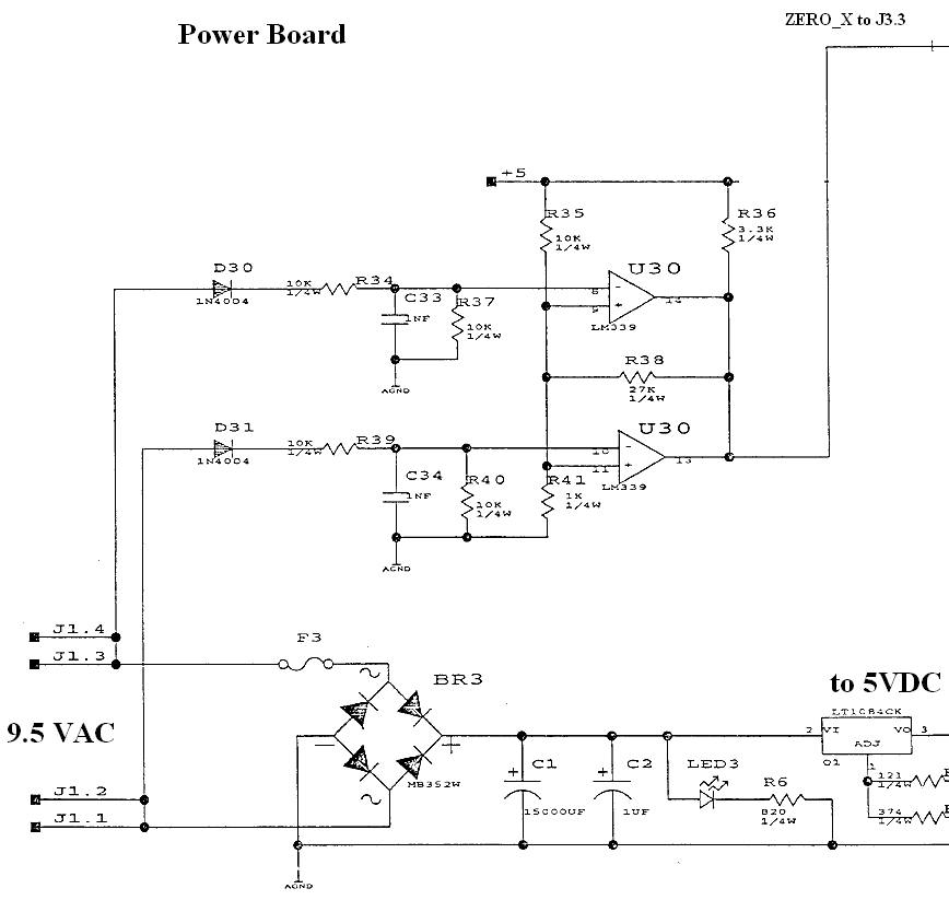
Testing usually happens from the end to the beginning, to see where the signal(s) reappear. But it really does not matter where you start looking for the zero cross signal. On the Power board, there are 2 circuits one to detect the positive and one to detect the negative zero cross. This circuit is connected to "agnd" (Analog Ground), so you should measure from "agnd" to some point on the above diagram. It is a small circuit, so this should not be too bad...
Good Luck!
Pfutz Home / Email Pfutz