This Capcom Service Bulletin applies to:
Pinball Magic, Airborne, Breakshot, Flipper Football, & KingPin Pinball
Back to all Capcom Pinball Service Bulletins
 COIN-OP, INC.
(Pinball Division is out of business)
COIN-OP, INC.
RS232/coin
meter PCB upgrade kit
PART NUMBER K-008-1
Parts needed
RS232/coin
meter PCB††††† Part #† A0019501
Serial
data cable††††††††††††††† Part #†† C-00197
Power
cable†††††††† ††††††††††††††Part #††
C-00196
Spacers
(4)†††††††††††††††††††††††† Part #† PL00108-04
Screws
(4)††††††††††††††††††††††††† Part #† SC00121-08
Schematics††††††††††††† †††††††††††† Part # A0019501
Instruction
sheet†††† †††††††††††† Part#
ďNOTEĒ†† ††††††††††††† GAME† MUST HAVE†
(for Pinball Magic) SOFTWARE VERSION V1.03 OR LATER. Tools needed Soldering
iron Solder Philips
screwdriver †ľĒ nut driver Wire/cable
ties Reason for kit This
kit is used to add a coin meter to the game.†
We have had requests from some operators to include these features. Estimated completion time 45
minutes. Procedure 1) Make sure that you have all
of the parts that your supposed to have in the kit, and make sure that nothings
broken.† If your looking at lots of
small pieces right now chances are there is a problem because there isnít
supposed to be any.† If there are any
missing or damaged parts please contact your local CAPCOM distributor. 2) Turn power off to the game
and unplug it from the wall. 3) Open the coin door, and
remove the playfield glass hold down bracket. 4) Carefully remove the glass
and set it in a safe location. 5) Raise the playfield to itís
vertical position. 6) Locate the key to the
backbox.† Insert the key into the lock
at the top of the backbox and turn it fully clockwise.† Lift up on the backglass and swing it out
towards the front of the game.†
Carefully remove the backglass and set it aside in a safe place. 7) Open the lamp door by
lifting the latch, and swing the door completely open. 8) Open the dot matrix display
panel by pushing the two latches, located above the speaker enclosures, out
towards the sides of the backbox. 9) Connect the serial data
cable to connector J3 on the CPU PCB. 10) Route the cable through the
bottom of the backbox into the bottom cabinet.†
Run the cable along the inside left wall until it reaches the coin door.
Make sure that the cable will not get pinched in the backbox. Use wire ties to
secure the cable. 11) Close and latch the dot
matrix panel and the backbox lamp door.†
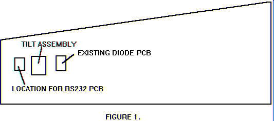
Replace the backglass. 12) Attach the PCB (with the
screws and spacers provided) to the inside left wall.† Refer to figure 1 for the proper location. 13) Connect the serial data
cable (the other end was just connected to the CPU) to connector J9 on the
RS232 PCB. 14) Connect one side of the power
cable to connector J5 on the diode PCB (see figure 1), and connect the other
end of the cable to J8 on the RS232 PCB. 15) You are now ready to install
your meters.