This Capcom Service Bulletin applies to:
Pinball Magic, Airborne, Breakshot, & KingPin Pinball
Back to all Capcom Pinball Service Bulletins
 COIN-OP, INC.
(Pinball Division is out of business)
COIN-OP, INC.
CAPCOM
COIN-OP,а INC.
3311 N.
KENNICOTT AVE.
ARLINGTON
HEIGHTS, IL 60004
K-010 Dot Matrix Display Upgrade Kit
PM00138
Parts needed
Displayаааааааааааааааа ааааааааааааааааааааааааааааа Part # DP00102
Dot matrix power supply
PCBаа ааааааа Part
# A0015500
Main power cable аааааааааааааааааааааааааааа Part # C00224
Display power cableаааааааа ааааааааааааааааа Part
# C00182
Screws (4)аааааааааааааааааа ааааааааааааааааааааааа Part # SC00100-04
Instructionsааа аааа аааааааааааааааааааааааааааааа Part # PM00138
Serial numbers affected
Any games with a УPB1Ф
prefix on the serial number.
Tools needed
Philips screwdriver
Wire cutters
Wire/cable ties
Reason for kit
We have gone from a display
with an on board power supply to one that has a separate power supply PC board.
ааа
Procedure
1. Check to ensure that all
parts are present, and intact.а If there
are any missing orааааааааа
ааа damage parts please contact your local CAPCOM distributor.
2. Turn the power to the
game off, and unplug it from the wall.
3. Locate the key to the
backbox.а Insert the key into the lock
at the top of the
ааа backbox and turn it fully clockwise.а Lift up on the backglass and swing it out
ааа towards the front of the game.а
Carefully remove the backglass and set it aside in
ааа a safe place.
4. Open the lamp door by
lifting the latch, and swing it completely open.
5. Open the dot matrix
display panel by pushing the two latches, located above the
ааа speaker enclosures, out towards the sides of the backbox.
6. Disconnect the ribbon
cable and power supply cable from the display.а
This power
ааа supply cable should now be removed from the game and
discarded.а It connects
ааа from the dot matrix display to СJ6Т on the main power supply
PCB.а At this point
ааа cable ties will need to be cut in order to remove the
cable.а Do not re-clamp the
ааа wires at this point.
7. Remove the four (4)
screws that secure the metal cover for the display, and set the
ааа cover (with the CPU PCB still attached) in the back box.
8. Remove the old dot matrix
display and replace it with the new one.
9. Replace the metal cover,
and screw it down.а Make sure that the
speaker wires are
ааа not pinched under the cover when you replace it.
10. Place the display power
board on the four standoffs to the left of the CPU.а Make
ааааа sure that the PCB is oriented in such a way that connectors,
СJ1Т and СJ2Т, are
ааааа on the side of the PC board that is closest to the backbox
wall at this point (see
ааааа FIGURE 1).а Secure the
display power supply board to the standoffs with theа
ааааа four (4) screws provided.
11. Attach the display power
cable from connector СJ2Т on the dot matrix power
ааааа supply board to connector СJ4Т on the dot matrix display.
12. Connect the small ribbon
cable from the CPU PCB to connector СJ5Т on the
ааааа display.
13. Attach the main power
cable to connector СJ1Т on the display power board.
ааааа Connect the opposite end to the power board at connector
СJ6Т.
14. Verify that all
connectors are in the correct location, and that they are all seated
ааааа properly.
15. You will now want to
make sure that the cables you have used are routed in such
ааааа a way that they will not get pinched when the dot matrix
display panel is closed.а
ааааа Use cable ties to secure the wires in place.
16. Close and latch the dot
matrix display panel and the backbox lamp door.а
аааааа Replace and lock the backglass in place.
17. SMOKE TEST!а Plug in the game and turn it on.а You should now have a fully
ааааа functional display.а
If the display is not working at this point, turn the game off
ааааа and verify that all connectors are in the proper
locations.а If the display is still
ааааа not working contact your distributor for further help.
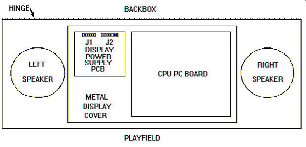
FIGURE 1