This Capcom Service Bulletin applies to:
Pinball Magic, Airborne, Breakshot, Flipper Football, & KingPin Pinball
Back to all Capcom Pinball Service Bulletins
 COIN-OP, INC.
(Pinball Division is out of business)
COIN-OP, INC.
K-008-2ааааа RS232/coin meter/printer, PCB upgrade
kit
Reason for kit
This kit is used for adding
a coin meter, and a printer port to any CAPCOM Pinball games.
Parts list
RS232/coin meter/ptr PCB аа Part # A0019501
Serial data cable аааааааааааааааааа Part # C-00197
Printer interface cableа аааааааа Part
# C-00195
Power cableаааааа аааааааааааааааааааа Part
# C-00196
Spacers (4)ааааааааааааааааа аааааааааа Part # PL00108-04
Screws (4)аааааааааааааааааааааааа ааааа Part # SC00121-08
Switch bracketааааааааааааааа ааааааа Part # MT00321-2
Schematicsаааа аааааааа
аааааааааааааа Part # A0019501
Instruction sheetааааааа ааааааааааа Part # PM00137а
rev 3
ааааааааааааааааааааааааааааааааааааааааааааааа
Serial numbers affected
All pinball games.а PINBALL MAGIC(tm) serial
numbers PB100001 through PB100040 will require kit # K-011, which includes: 1
Door switch actuator #MT00329, AND 1 Switch bracket hole template #PM00143.
NOTE:ааааааааааа GAME MUST HAVE (Pinball Magic) SOFTWARE VERSION V1.04 OR LATER
Tools neededааааааааааааааааааааааааааааааааааааааааааааааааа
Soldering iron and solderаааааааааааааааааа
Philips screwdriverаааааааааааааааа
1/4Ф nut driver
Cable tiesаааааааааааааааааааааааааааааа ааааааааааааааааааааааааааааааааааааааааааааааааааааааааааа
Procedure
1. Inventory physical parts
against the parts list above.а Please
contact your local
ааа CAPCOM Distributor regarding any missing or damaged parts.
2. Turn power off to the
game and unplug it from the wall.
3. Open the coin door, and
remove the playfield glass hold down bracket.
4. Carefully remove the
playfield glass and set it in a safe location.
5. Locate the key to the
backbox.а Insert the key into the lock
at the top of the
ааа backbox and turn it fully clockwise.а Lift up on the backglass and swing it out
ааа towards the front of the game.а
Carefully remove the backglass and set it aside in
ааа a safe place.
6. Open the lamp insert
panel by lifting the latch, and swing it open.
7. Raise the playfield to
itТs vertical position.
8. Open the dot matrix
display panel by pushing the two latches, located above the
ааа speaker enclosures, out towards the sides of the backbox.а Now lower the displayаааа
ааа panel.
9. Connect the serial data
cable to connector J3 on the CPU PCB.
10. Route the cable around
the CPU board dressing the cable to the existing cable
ааааа with 2 cable ties at the corners of the CPU PCB.
11. Route the cable through
the bottom of the backbox and into the bottom cabinet.а
ааааа Run the cable along the inside left wall until it reaches the
coin door. Make sure
ааааа that the cable can not be pinched in the backbox, and that
there is enough slack
ааааа to lower the backbox without ripping the cable off of the
CPU.а Use wire ties to
ааааа secure the cable every 6Ф.
12. Close and latch the dot
matrix display panel and the backbox lamp insert panel.а
аааааа Replace
the backglass and lock it in place.
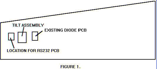
13. Attach the RS232 PCB
(with the screws and spacers provided) to the inside leftааааа
ааааа wall.а Refer to figure
1 for the proper location.
14. Connect the serial data
cable (the other end was just connected to the CPU in STEP 9) to connector J9
on the RS232 PCB.
15. If there is a connector
already connected to J5 on the diode PCB (see figure 1)
ааааа proceed to step 17.
16. Connect one side ofа the power cable to connector J5 on the diode
PCB (see
аааааа figure 1), and connect the other end of the cable to J8 on
the RS232/coin
аааааа meter/printer PCB.
17. Remove the coin door
switch and the 50v interlock switch from the bracket on
ааааа the inside of the cabinet.а
These are located on the bottom left hand side of the
ааааа coin door opening.
18. Remove and discard the
metal switch bracket.
19. Attach the new switch
bracket to the cabinet in place of the one that you just
ааааа removed.
20. Place the interlock
switch and the coin door interlock switch into the bracket,аа
ааааа and connect the switches back up.
21. Remove the two hex mounting
screws on the switch bracket.а Use these
screws to
ааааа attach the printer interface cable to the switch bracket.
22. Now connect the cable to
connector J1 on the RS232 PCB.
23. There is a 12 pin male
Molex connector that is part of the main wiring harness
аааааа connected to J5 of the diode PCB.а Disconnect and reconnect to J8 of the
аааааа RS232 PCB.
24. To install a coin meter,
attach the meter to the RS232 PCB at connector J7.ааа
25. You are now printer and
meter ready.а Refer to the REPORTS
section of yourааааааааааа
аааааа game manual for information on printer setup.
NOTE:
CITIZEN IDP 562 DOT MATRIX
PRINTERа
Attach a СSerial Printer
CableТ from your printer to the printer connection the front door.
LAP TOP
Attach a СNULL MODEM CABLEТ
from your lap top to the printer connection at the front door.
K-008-2/PM00137
rev 3