This Capcom Service Bulletin applies to:
Pinball Magic, Airborne, Breakshot, Flipper Football, & KingPin Pinball
Back to all Capcom Pinball Service Bulletins
 COIN-OP, INC.
(Pinball Division is out of business)
COIN-OP, INC.
K-008-5 RS232/COIN METER/NSM PTR/ PCB upgrade kit
Reason for kit
This kit is used for adding
a coin meter, and a printer port to any CAPCOM Pinball game.
Parts list
RS232/coin meter/ptr PCB Part #
A0019501
Serial data/ ptr cable Part # C-00198
Power cable Part # C-00196
Spacers (4) Part # PL00108-04
Screws (4) Part
# SC00121-08
Switch bracket Part
# MT00321-2
Schematics Part
# A0019501
Instruction sheet
Part # PM00140 rev 2
Serial numbers affected
All pinball games. PINBALL MAGICﺿ Serial
numbers PB100001 through PB10040 will
require kit # K-011 which includes: 1
Door switch actuator #MT00329, and 1
Switch bracket hole template #PM00143.
NOTE: GAME MUST HAVE (for Pinball Magic) SOFTWARE VERSION V1.04 OR LATER
Tools needed
Soldering iron and solder
Philips screwdriver
1/4 nut driver
Cable ties
Procedure
1. Inventory physical parts
against parts list above. Please
contact your local
CAPCOM Distributor regarding any missing or damaged parts..
2. Turn power off to the
game, and unplug it from the wall.
3. Open the coin door, and
remove the playfield glass hold down bracket.
4. Carefully remove the
playfield glass and set it in a safe location.
5. Locate the key to the
backbox. Insert the key into the lock
at the top of the
backbox and turn it fully clockwise. Lift up on the backglass and swing it out
towards the front of the game.
Carefully remove the backglass and set it aside in
a safe place.
6. Open the lamp insert
panel by lifting the latch, and swing it completely open.
7. Raise the playfield to
its vertical position.
8. Open the dot matrix
display panel by pushing the two latches, located above the
speaker enclosures, out towards the sides of the backbox. Now lower the display
panel.
9. Connect the single end
connector of the serial data cable to
connector J3 on the
CPU PCB.
10. Route the cable around
the CPU board dressing the cable to existing cable with
2 cable ties at the corners of the CPU PCB.
11. Route the cable through
the bottom of the backbox and into the bottom cabinet.
Run the cable along the inside left wall until it reaches the
coin door. Make sure
that the cable will not get pinched in the backbox, and there
is enough slack to
lower the backbox without ripping the cable off of the
CPU. Use wire ties to
secure the cable every 6.
12. Close and latch the dot
matrix display panel and the backbox lamp insert panel.
Replace and lock the backglass.
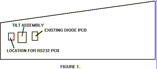
13. Attach the RS232 PCB
(with the screws and spacers provided) to the inside left
wall. Refer to figure
1 for the proper location.
14. Connect the serial data
cable 14 pin connector (the other end was just connected
to the CPU at step 9) to connector J9 on the RS232 PCB. Dress the cable every
6 with cable ties.
15. Now connect the 10 pin
connector on the same cable to connector J1 on the
RS232 PCB.
16. If there is a cable
connected to J5 on the diode PCB go to step 19.
NOTE: [Block diagrams
for: games with a power connector on J5 of diode PCB
see page 4. Block diagrams for: games without a power
connector on J5 of diode
PCB see page 5.]
17. Connect one side of the
power cable to connector J5 on the diode PCB (see
figure 1), and connect the other end of the cable to J8 on
the RS232 PCB.
18. Take the 4 pin connector
with the single yellow wire comming from the serial
data/ printer cable, and remove the wire from the 4 pin
connector. Splice this
yellow wire to the yellow wire in the power cable just
installed in step 17.
19. Remove the coin door
switch and the 50v interlock switch from the bracket on
the inside of the cabinet.
These are located on the bottom left hand side of the
coin door opening.
20. Remove and discard the
metal switch bracket.
21. Attach the new switch
bracket to the cabinet in place of the one that you just
removed.
22. Place the interlock
switch and the coin door interlock switch into the bracket,
connect the switches back up.
23. Remove the two hex
mounting screws on the switch bracket.
Use these screws to
attach the printer interface cable to the switch bracket.
24. There is a 12 pin male
Molex connector that is part of the main wiring harness
connected to J5 of the diode PCB. Disconnect and reconnect this 12 pin
connector to J8 on the RS232/coin meter /Printer PCB.
25. Separate the 12 pin
male/ female Molex connector that connects the coin door to
the main wiring harness.
Connect the male end to J2, and the female end to
P1 on the RS232 PCB.
26. To install a coin meter,
attach the meter to the RS232 PCB at connector J7.
27. You are now ready to
connect your NSM data printer 3000.
Refer to the reports
section of your game manual for information on printer
setup.
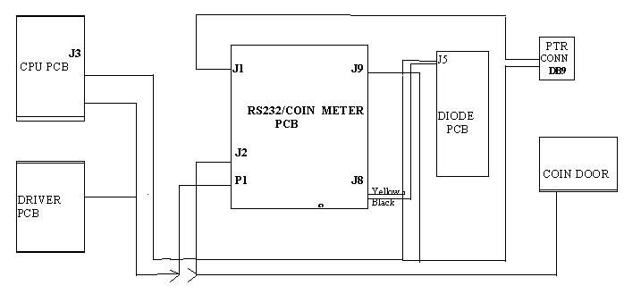
The followinging is a
diagram for games with a power cable connected to J5 on the diode PCB.
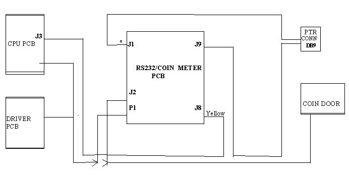
The follow is a diagram for
games with-out a power cable
connected to either J4 or J5 on the diode PCB.
K-008-5/PM00140
rev 2