This Capcom Service Bulletin applies to:
Pinball Magic, Airborne, & Breakshot Pinball
Back to all Capcom Pinball Service Bulletins
 COIN-OP, INC.
(Pinball Division is out of business)
COIN-OP, INC.
August X,
1996
Game: Pinball Magic,
Airborne, and Breakshot
Potential
Problem: Circuit breaker tripping at
turn on.
Dear
Distributor,
The
purpose of this letter is to show how to install a thermistor (part number
RS00120-01) to prevent a circuit breaker from tripping at turn on.
Tools
required:
Wire
Cutters
Wire
Strippers
Soldering
Iron
Solder
Approximately
4” Of 1/8” Diameter Heat Shrink Tubing
Electrical
Tape
To install
the RS00120-01 thermal resistor (thermistor) perform the following steps for
the appropriate game.
PINBALL
MAGIC or AIRBORNE
1.
WARNING!
Turn game power switch off and unplug line cord from the wall!
2.
Remove the
playfield glass and set aside in a safe location.
3.
Raise the
playfield to its full upright position.
4.
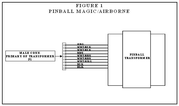
On the
transformer in the lower cabinet locate the black wire that connects from the
primary windings to pin 1 of the 9 pin male Molex connector (reference figure
1).
5.
Cut the
black wire midway between the transformer and the 9 pin male Molex connector.
6.
Strip
approximately 1” of each new end created by cutting the black wire.
7.
Cut 2
pieces of heat shrink approximately 2” long out of the 1/8” diameter heat
shrink tube. Place 1 piece on each end
of the black wire.
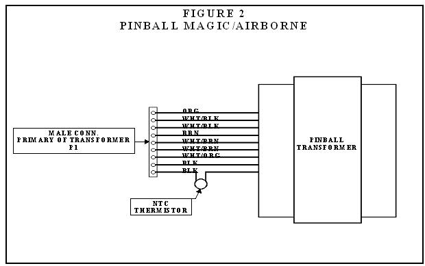
8.
Wrap one
end of the of the stripped ends of the black wire around one leg of the
thermistor. Solder it in place. Pull the heat shrink tube up over the
connection and shrink in place. After
the tube has been shrunk use electrical tape at the top and bottom of the
tubing to ensure that it is impossible for the tubing to move out of place.
9.
Repeat
step 8 for the other lead of the thermistor (reference figure 2).
BREAKSHOT
1.
WARNING!
Turn game power switch off and unplug line cord from the wall!
2.
Remove the
playfield glass and set aside in a safe location.
3.
Raise the
playfield to its full upright position.
4.
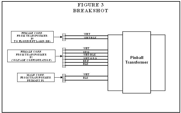
On the
transformer in the lower cabinet locate the black wire that connects from the
primary windings to pin 1 of the 3 pin male Molex connector (reference figure
3).
5.
Cut the
black wire midway between the transformer and the 3 pin male Molex connector.
6.
Strip
approximately 1” of each new end created by cutting the black wire.
7.
Cut 2
pieces of heat shrink approximately 2” long out of the 1/8” diameter heat
shrink tube. Place 1 piece on each end
of the black wire.
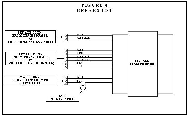
8.
Wrap one
end of the of the stripped ends of the black wire around one leg of the
thermistor. Solder it in place. Pull the heat shrink tube up over the
connection and shrink in place. After
the tube has been shrunk use electrical tape at the top and bottom of the
tubing to ensure that it is impossible for the tubing to move out of place.
9.
Repeat
step 8 for the other lead of the thermistor (reference figure 4).