 WMS Doctor Who Pinball, Install a Moving Dalek Head

|

|
WMS Doctor Who Pinball, Install a Moving Dalek Head
|

|
It is true that ALL Doctor Who software (hence all Doctor Who games) support the Dalek moving head.
This is because about 100 prototype games exist with this feature.
However in order to be "downwards" compatible, the New software will automatically detect if the moving head exists.
It does so every time you turn on the game.
It first assumes that you do not have a moving Dalek head, the on power-up the game turns on the motor to turn the head.
If the center (or home) switch is not activated within a certain time limit, you definitely do not have a moving head.
If the center switch is activated, it turns off the motor and activates the Dalek head game adjust and diagnostic.
This has 2 minor side effects Note: Connector-pin J206-0 is a typo, it should be pin 9 (J206-9) not pin 0. Pfutz Update: 06/09/2021 Update: 02/12/2000 Update: 03/18/2000 Here is Richard H. Poser II that has already converted his Stationary Dalek Head to a moving Dalek Head and Documented this procedure!. Update: 03/15/2002 Al Warner has developed a "Dr. Who Dalek swivel kit" alsarcade@home.com or sales@alsarcade.com It was advertised in a in Mr.Pinball (4805 Marabow Circle, Salt Lake City, UT 84117-5419, (801) 277-6296, (801) 277-0888 FAX) parts for sale back in Feb 2001. At the time only about 8 kits were made... Update: 03/15/2002 News group Articles about the "Dalek Moving head" or about the "Dr. Who Dalek swivel Kit" or about the "Wobbly Kit" Update: 02/10/2004 Wobble head #1 (From "Basement Arcade Classics" ) "(Dead Link) Basement Arcade Classics, Wobble head" or "(Dead link) Wobble head (details)" Update: 07/31/2011 Wobble head #2 (From "Basement Arcade Classics" ) "Basement Arcade Classics, Wobble head - buy it now (as of 10/01/2011)" "Basement Arcade Classics, Wobble head (making of)" |
|
|
|
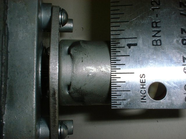
 Click on image to enlarge #5 - 12VDC Motor from Williams or For Amusements Only (Williams Parts) or Multi Products Co Spec #3238 |
Question:
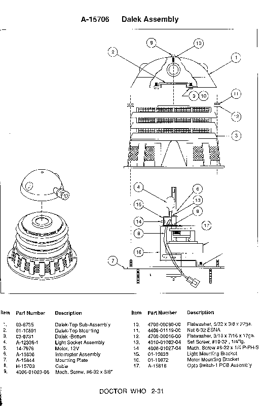
In the game "Doctor WHO", the prototypes had a motor to move the Dalek robot at the top of the backglass, but this feature did not make it into production games. Is there, laying around Williams somewhere, a schematic for the motor assembly used in this moving-Dalek feature? Can I get a copy of it? I someday will get a Doctor WHO game, and want to restore the moving Dalek... Answer: Uncle Willy was only able to find out the simplest of details on this. Apparently the support for the moving Dalek head is still in the production software, with an adjustment to enable it. The motor and gear assembly must have had some sort of cam arrangement to turn the single-direction motor movements into reciprocating head movements, but Uncle Willy couldn't find out much more about that (other than to note that the part number was 14-7976). The motor was driven like a flasher, with its voltage coming from J107-5,6 and its drive coming from Q26/J122-1 (Blu-Brn wire, solenoid number 25). There was an optical switch, presumably to detect the "home" position of the head, that was connected as switch 81 (Column8/U20-11/J206-0/Grn-Gry; Row1/U18-11/J208-1/Wht-Brn). See scan of the prototype instruction manual page that shows this whole assembly (on right) To see and hear a moving Dalek Head from a prototype Game (745Kbyte MPG file) 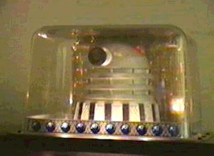
|
|
|
|
|
Click on any image to enlarge it! |
|

|
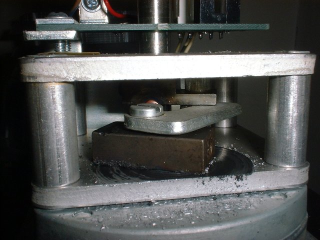
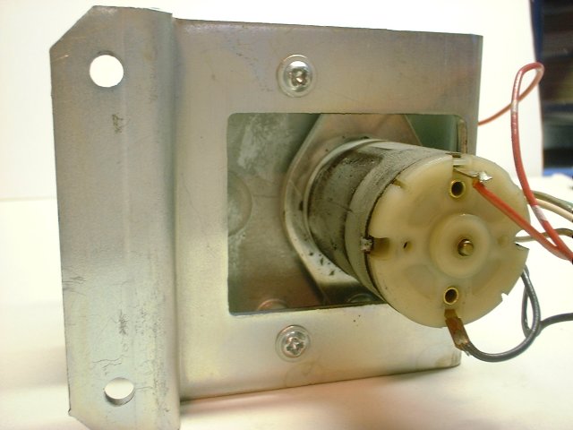
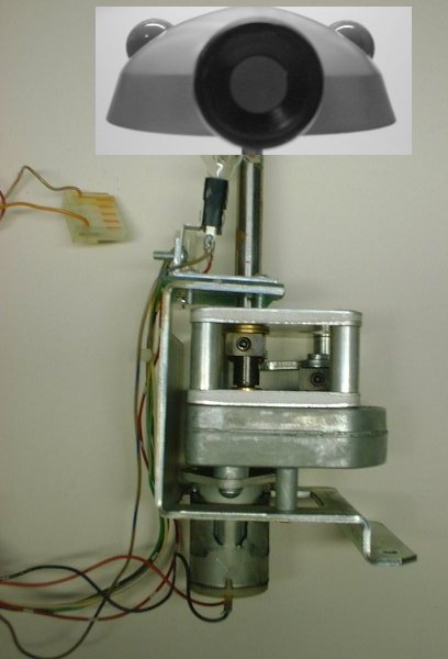
Here are the basic parts: (From top to Bottom) ------------------------------------- The Shaft to head of the Dalek The Front facing opto interrupter The flasher next to the interrupter The Offset cam The 24VDC motor (run at +20VDC) In the Back Box (under the head) ------------------------------------- A Motor Driver board A resistor for the flasher |
|
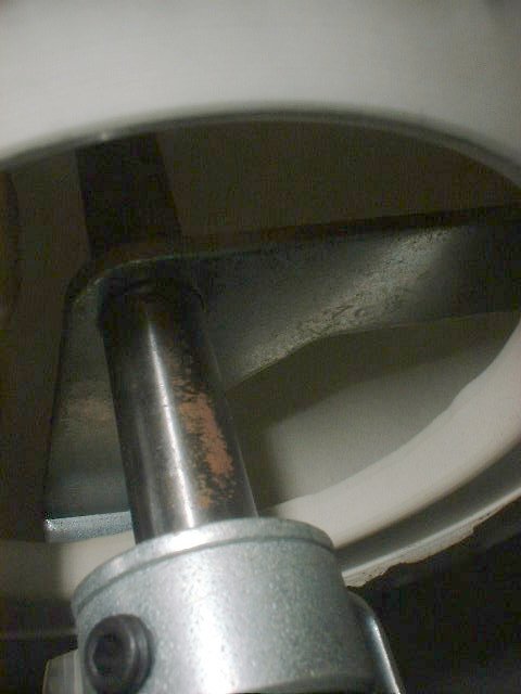
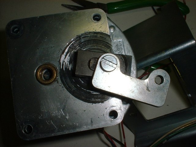
The Offset cam (From Bottom to Top) ------------------------------------- A Bar is connected to the motor shaft. This moves in a circle. A flat L-bracket is attached to this bar and moves in a circle with the bar. The other end of the 'L' is attached to another bar from the Dalek head shaft. I do not know the proportions, but the correct ones rotate the Dalek head about 90 degrees. 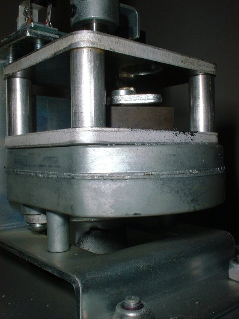

|
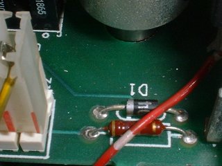
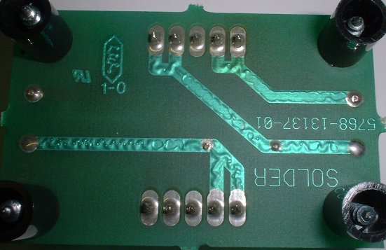
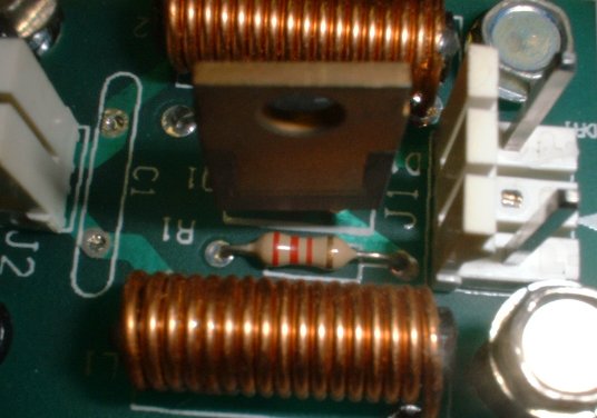
Under the Dalek Head (In the Back Box) -------------------------------------- It was here that they mounted the Motor Driver board (left) and the Flasher Resistor (right). 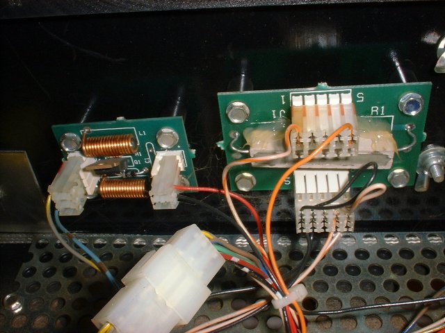
|
Close Up of the Circuit Board in the Dalek Head. 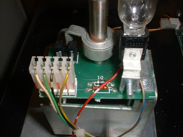
|
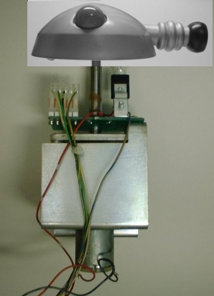
- How the head connects to the rod. There is a triangular plate inside the head that the rod passes through. A notch in the plate and rod keeps them from slipping. Also, a screw goes through the top of the Dalek head into a hole at the top of the rod. See pics: 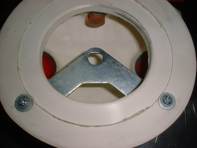

|
|
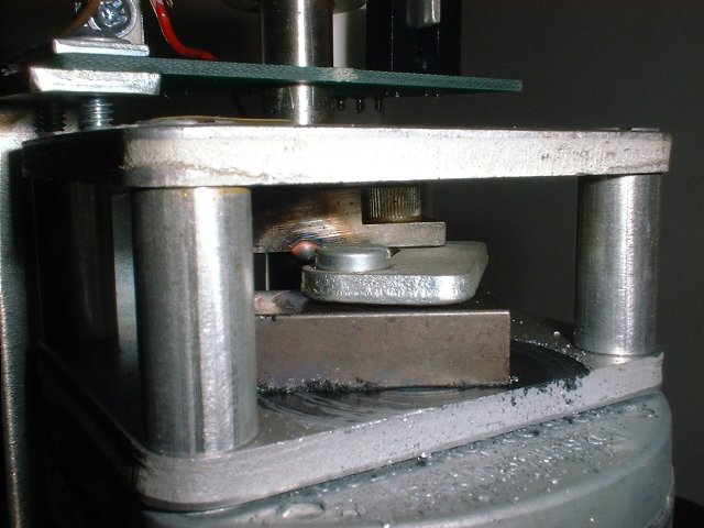
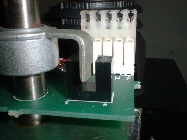
- How the rod stays stationary. There are two plates positioned above the gear box with 4, 7/8" aluminum spacers between them. Within this gap is the arm mechanism that creates the back an forth movement. See: 

|
The two plates both have holes in them to let the rod pass through. The top plate has a brass (?) sleeve that will just barely let the rod pass through and still turn. See: 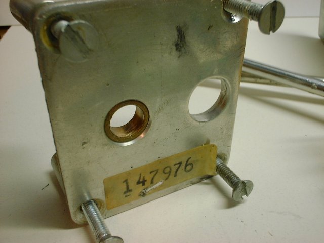
|
The bottom plate has a similar brass sleeve. However, the bottom of the rod is tapered a bit, so the rod doesn't actually go all the way through the plate. 
|
The housing that the whole assembly sits upon: 
|
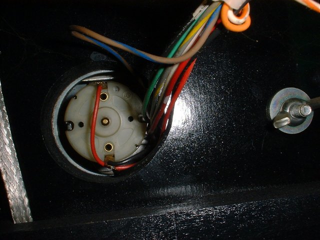
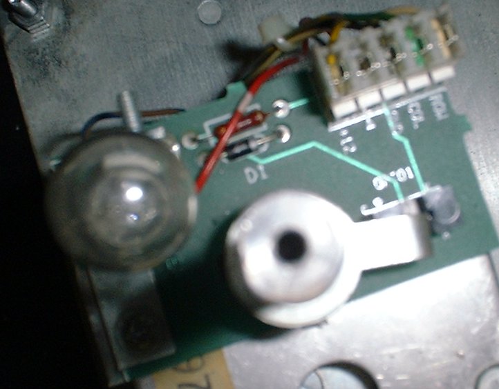
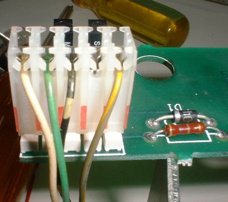
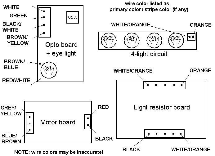
There are a few more scans of various parts Opto circuit board and wires: 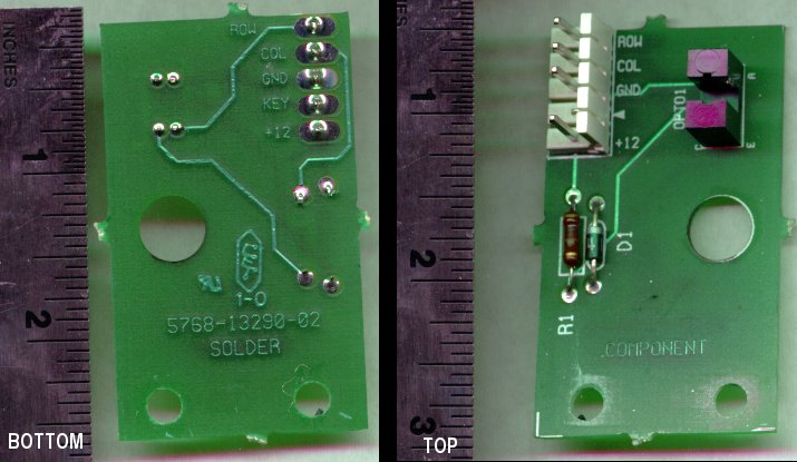
|
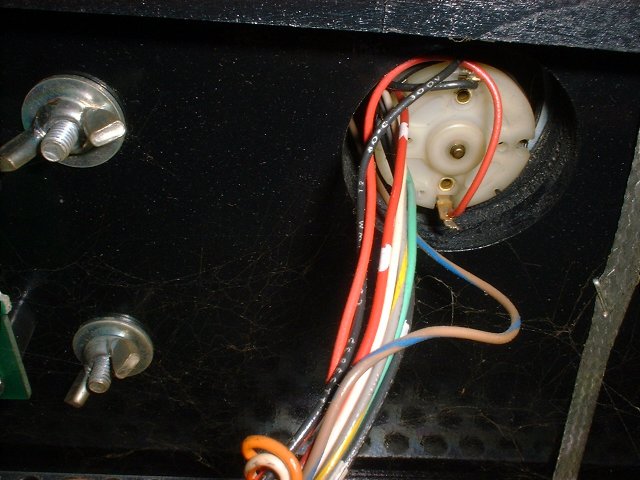
Ring with a tab to trip the opto sensor: 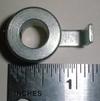

|
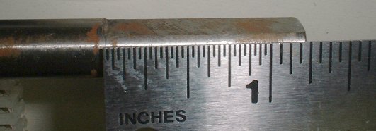
Motor measurements 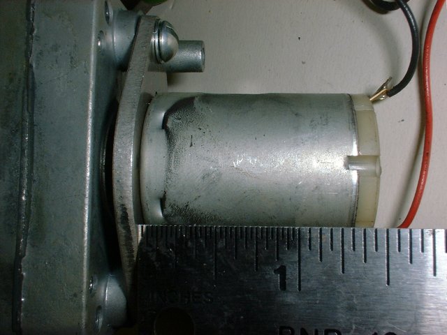
|
One of the arm hinges to make the back-and-forth motion: 
|
The entire motor assembly, disemboweled from the game: (I have superimposed the Dalek head over these pics to keep the orientation clear) 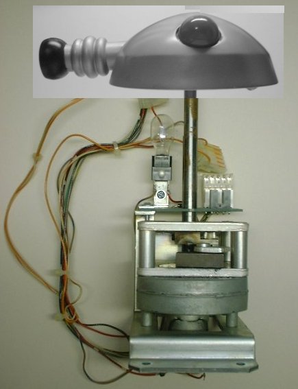

|
|
|
1.500 Megabyte MPG file 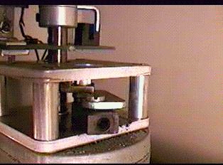
|
0.845 Megabyte MPG file 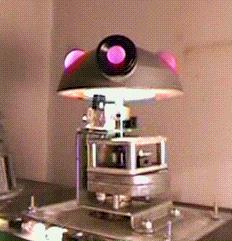
|
|
Of course, you can try & build the motor it yourself, or perhaps you can buy one at a store that sells motors and gear boxes (i.e. a hobby store).
Maybe even see if you can find a small electric fans that moves left & right?
OR
For Amusements Only (Williams Parts)
OR
Williams did use a place called
Multi Products Co
(5301 21st St, Racine WI 53406)
262-554-3700.
Although Multi products did not make the oscillating 'gears' for the Dalek head, they did make alot of motors & gear boxes for other Pinballs.
Other possible Sources of motors: Edmund Scientific DigiKey (search for "motor rpm") All Electronics (click on "motors(gear)") HappControls .com (search for "motor") PittMan Motors Sun Micro Motor Technology LTD Thomas Pain Registry search for sources of motors: http://www92.thomasregister.com/ss/(gearboxes) Update: 02/16/2000, Multi-products does have an oscillation motor estimated at $??? with an estimate of ?-? weeks to manufacture, plus you would have to modify/machine it (change the ?shaft?) to work in the head. Plus, The size might be too big (5 inches) to fit inside the head. But who wrote the book that said it HAD to be inside the Head (I stand corrected by the many pinball fans). It could be located in the backbox, below the head. OR in a pedestal (box) between the bottom of the Head and the top of the backbox. The head can also be repositioned left, right, forward or back (wood filler and paint can hide the old holes) to make the motor fit (make a paper template of the motor and see if you can make it fit). IF you are an enthusiast, buy a full sized Dalek (or maybe two Daleks), run the wires to it, and make their head(s) and eye pieces move (no fair wiggling their ears!). IF you are an extremist, put lasers in all the Daleks Eye pieces, fill the room with a light haze (like the Laser Zones) and watch the light shows.... Update: 02/19/2000, Some people have asked Multi products about just the motor (from A-15706 Dalek Assembly picture, part 5, 14-7976 "Motor 12V"). They have said that it cost about $125 (please ask for current price) and about 3-4 weeks to manufacture. The spec number to order (or ask about) is 3238. Also, the motor is still available (as of 02/18/2000) from Williams, at a cost of about $90. (Only 16 more parts to go...) - Motor Voltage: 6-24VDC, (well here is a trick, the motor is documented at 12VDC. But, is really a 24VDC motor. It was powered from the unregulated 20VDC power supply, if you get another motor be sure that can handle 24VDC!), - Motor speed: about 20 RPM (at 20VDC) - Degrees of rotation: about 60 (30 degrees left, 30 degrees right) |
|
|
|
|
|
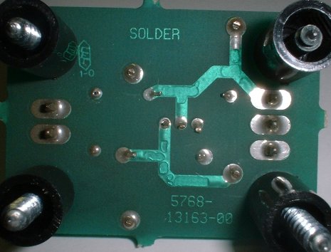
The Large Circuit Board (for the Flasher) 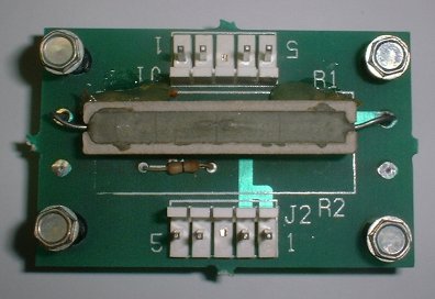
|
The Small Circuit Board (the Motor Driver Board) 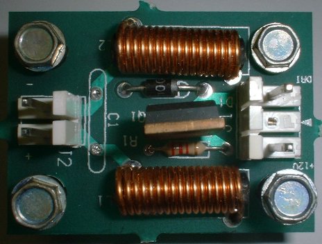

|
|
|